
The Global Positioning System (GPS) is a worldwide radio-navigation system formed from a constellation of 24 satellites that continuously orbit the earth. Each GPS satellite has on board several atomic clocks that are precisely synchronized to Universal Time Coordinated (UTC) provided by the U.S. Naval Observatory (USNO). Coded signals are broadcast by each of the satellites with the exact time and position of the satellite. All GPS receivers use an antenna to receive these signals. By using a GPS receiver optimized for time and not position, it is possible to get extremely precise time synchronization with the satellite’s atomic clocks.
The signals from the GPS satellites operate in the “semi-visible” spectrum of the L1 band (1575.42 MHz) with a minimum signal level of -162.0 dBW. With this very low signal strength, the GPS antenna must be able to “see” the sky to acquire the signals. Practically speaking, the antenna must have a clear view of the sky and thus be mounted on a roof, or in some cases in a window. The antennas are relatively small (coffee cup size or smaller) and are typically connected to the GPS receiver via coaxial cable.
Since the GPS signal is very weak, the antenna usually amplifies the signal to drive it through the cable to the receiver. Antenna cables, however, offer some resistance, and the GPS signal strength will attenuate as it travels down the cable. GPS receiver sensitivity is finite, so if the cable length is too long, the signal will be too weak for the receiver to detect it. Consequently, it is very important to know the distance in advance between the antenna and the receiver so that the proper cable solution can be installed.
Masterclock GPS Antenna and Cable Options
GPS Antenna Placement & Mounting
There are two basic antenna types used with GPS timing receivers: roof mounted and window mounted. The roof mounted antenna is required for more accurate GPS clocks since at least three satellites are required to be in view at all times to maintain timing accuracy (typically nanoseconds to UTC). The window mounted antenna is applicable for network time servers, which operate with a lesser degree of accuracy (typically microseconds or, in some cases, low milliseconds to UTC) and can function with as few as one intermittent satellite in view.
The roof mounted antenna is always preferable, as it—by nature of its location—has the best view of the sky. A variation on the roof antenna is the GPS down/up converter used for very long cable runs. This is a special GPS antenna that receives the GPS signal and down converts it to a lower frequency that is then sent down the cable. Next to the GPS receiver is an up converter that converts the signal back to the original frequency and delivers it to the GPS receiver. This process is transparent to the GPS receiver.
Roof Antenna Placement
When selecting a site for the roof antenna, find an outdoor location that provides full 360-degree visibility of the horizon. In most cases, this means locating the antenna as high as possible, such as on the roof. Any obstructions may degrade unit performance by blocking the satellite signals. Blocked signals can increase the time for satellite acquisition, or prevent acquisition altogether.
A short mounting mast and hose clamps are provided with the roof antenna to mount the antenna to a pole or the peak of a building. The antenna mounting mast and clamps are well suited to attach the antenna to a vent pipe or mast affixed to the roof. The pipe must be rigid and able to withstand high winds without flexing.
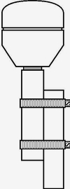
Typical Roof Antenna Mounting
GPS receivers can be susceptible to reflected GPS signals called multipath. Multipath interference is caused by reflected signals that arrive at the antenna out of phase with the direct signal. This interference is most pronounced at low elevation angles from 10 to 20 degrees above the horizon. The height of the mast/antenna may be extended upward to prevent multipath interference. The antenna should also be at least three to six feet (1-2 m) from a reflecting surface.
Window Antenna Placement
The window mount antenna is suitable for use only with network time server products equipped with appropriate versions of firmware. For window mounted antenna installations, it is best to use a window with the best view of the sky. For windows with equivalent views, orientations that face the equator are preferred. Generally, more satellites will be in view toward the equator than away from it; east- or west-facing windows will also work. Polar-facing windows will also work but in general are not preferred. Windows that have the best view of the sky are always preferred, regardless of orientation.
Attach the antenna above the window sill rather than at the top of the window. This will improve the upward visibility from the antenna to the sky. Note that some window glazing treatments may reduce or block the GPS signals, preventing the time server from acquiring the time.
Indoor Mounting Can Be Problematic
Obstructions may block signal reception if your GPS antenna is not properly located. Try to find an unobstructed view of the sky. In some cases, this can be accomplished by placing the included basic antenna adjacent to a window. However, in most cases, good reception will require mounting a standard antenna outside of the building, perhaps on a roof. It is possible that the system will operate indoors and under certain obstructions, but this can only be determined by trial and error, ultimately leading to a successful installation.
GPS AntennaCable Configurations/options
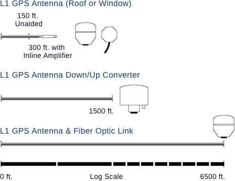
Antenna cabling solutions typically vary depending on how far the antenna is installed from the GPS receiver. 150 feet (45 m) is the unaided cable length limit for many GPS timing receivers. Adding a GPS inline amplifier extends the cable length an additional 150 feet (45 m). Beyond 300 feet (90 m), alternative methods may be used. Figure 3 highlights the cable lengths and the antenna solutions that enable them.
Cable Delay
GPS position as well as precise UTC time is determined at the point the GPS signals are received at the antenna. Since the antenna is typically attached to the GPS timing receiver via a cable, signal propagation delays through the cable cause the time calculated by the receiver to be slightly behind UTC. In GPS clocks with nanosecond and microsecond accuracy, this is a critical factor. In products such as network time servers, cable delay is not important because time transfer over IP networks degrades the time to the millisecond level.
Cable delay is a function of the cable type. RG-59 cable, for example, typically delays the signal 1.24 ns/ft. For 50 feet of cable (15 m), the delay would be 62 nanoseconds. Cable delay is removed by advancing the antenna signal inside the GPS receiver. In this example, advancing the signal +62 nanoseconds removes all cable latency. Solutions such as the GPS down/up converter also introduce signal latency, but this latency can also be removed by adjusting the signal. All precision GPS timing receivers with nanosecond or microsecond timing accuracy have the ability to compensate for cable delay.
Lightning Arrestor
In-line lightning arrestors are mounted on a low impedance ground between the antenna and the point where the cable enters the building. They require no additional power or wiring except the ground lead.
In-line Amplifier
In-line amplifiers overcome signal attenuation by amplifying the GPS signal, adding an additional 150 feet (45 m) in cable length. The inline amplifier attaches directly in line with the antenna cable and uses the same power as the antenna; no extra wiring is required.
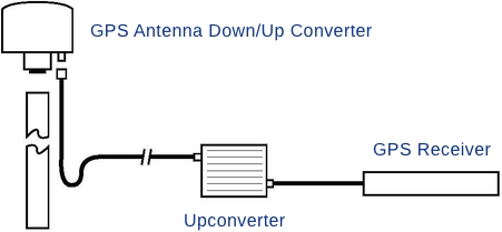
GPS Down/Up Converter
The GPS down/up converter makes cable runs of 250 to 1500 feet (75 m to 457 m) possible. GPS signal down conversion requires a special GPS antenna and corresponding signal up-converter. The antenna module converts the signal down to a lower frequency that is less susceptible to attenuation and transmits it the length of the cable to the up-converter. The up-converter restores the signal to the normal GPS signal frequency for the receiver. The down/up conversion process is transparent to the GPS receiver. As with any precision GPS timing receiver, only cable delay and down conversion delays need to be entered into the receiver. Power is supplied by the GPS receiver. In the case of bus-level GPS receivers, an external power supply is used. It is important to note that the cable used in GPS down/up conversion is different than the standard cable.
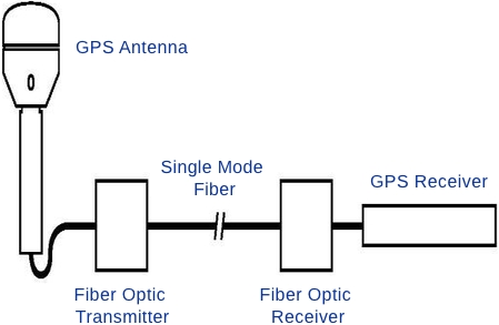
Fiber Optic Links
Fiber-optic connections function as a transparent link between the antenna and GPS receiver equipment. These links eliminate the limitations of copper systems by enabling longer transmission distances while retaining the highest level of signal quality. In addition, fiber optics provide several other significant network advantages, including simplified network design, ease of installation, and immunity from EMI/RFI and lightning.
Advanced Planning
It is time well spent to estimate in advance the cable length from the GPS antenna to the receiver for any planned installation. Cable lengths that are too short or too long can each introduce problems. In some cases, adding an inline amplifier and some extra cable may be a quick and economical solution. In other instances, retrofitting for a GPS down/up converter may be necessary, which will require installing a different cable type.
Keep in mind that some extra cable coiled in a ceiling leftover from overestimating the cable length is not necessarily negative. Provided you know the length of the total cable, the cable delay can be accounted for and the timing accuracy maintained.
Return to Knowledge Center to learn more.
Presentation by John Clark, CEO & Dr. Demetrios Matsakis, Chief ScientistTime Behind and Beyond the Clock